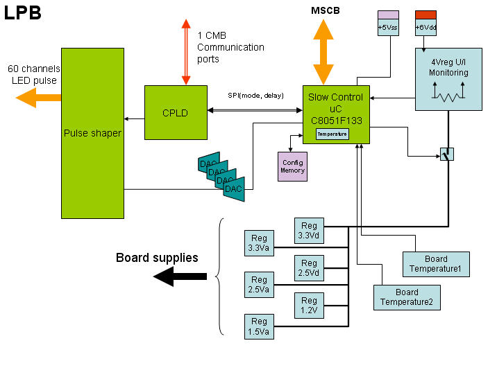
Light Pulser Board (LPB)
1
Purpose
The Light Pulser Board (LPB) handles the operation of the LED light flasher for all the MPPC channels of each crate of the FGD.
Description
Each LPB card handles 60 pulsing channels. Each channel fires 4 consecutive LEDs mounted at the far end of the wave shifting fibre at the opposite side of the MPPC. A single pulse with can be controlled through a delay (idx6) for all LED channels. The pulse hight is controllable by a DAC for group of 8 LED channels. The first LED channel is monnitored through an ADC channel (idx:7). The overall monitoring of the card is ensured by several ADCs for the differents voltages, current and temperature. While each card can read the internal relative humidity of the FGD box on the backplane, only a restricted number of crate have the RH sensor installed.
- Current list of LPBs address containing a RH sensor:
- FGD1 Bottom(C1, C3), TOP(C8), Right(14), Left(21)
- FGD2 Bottom(C27), TOP(C32), Right(38), Left(45)

Card Operation
- By default at power up the main elements of the card are kept unpowered.
- To power up the card:
- CTL register(idx:2) Set bit ^ 0 [0x01]
- CSR register(idx:3) will show bit ^ 0 = 1 (1=on, 0=off)
- To power down the card:
- CTL register(idx:2) Set bit ^ 7 [0x80] Manual Shutdown
- CSR register(idx:3) will show bit ^ 0 = 0 (1=on, 0=off)
- Global Delay(idx:6) set for all the 60 LED channels.
- Pulse hight DAC(idx:21-36) 12bit DAC, set for 4 consecutive LED channels corresponding to 16 LEDs or 1/6 of a layer.
- Issues
- The voltage monitoring is valid only once the card is powered up.
- The S/N is read incorrectly if the Vdd is not ON. This requires the turn on procedure to re-issue the ON once the WIENER's power supplies are turned on.
MSCB Registers
node253(0xFD)> r
  0: SerialN   32bit U        76500005 (0x048F4C25) byte
  1: Error     16bit U               6 (0x0006) byte
            Vss Slow Control Voltage    0x0001
            Iss Slow Control Current    0x0002
            Vdd Main +6V                0x0004
            Idd Main +6V                0x0008
            N/A                         0x0010
            I3.3V                       0x0020
            I1.8V                       0x0040
            uC Temperature              0x0080
            Vdd Switch fault            0x8000
  2: Control    8bit U               0 (0x00/00000000) byte
            Turn on Card                0x01
            N/A                         0x02
            N/A                         0x04
            TEST mode for CPLD          0x08
            EEPROM Save                 0x10
            EEPROM Restore              0x20
            N/A                         0x40
            Manual Shutdown card        0x80
  3: Status     8bit U               1 (0x01/00000001) byte
            Card ON                     0x01
            N/A                         0x02
            N/A                         0x04
            TEST mode Set for CPLD      0x08
            EEPROM Save complete        0x10
            EEPROM Restore complete     0x20
            System shutdown (card OFF)  0x40
            Manual Shutdown (card OFF)  0x80
  4: eepage     8bit U               0 (0x00/00000000) byte
            EEPROM page should be          0
  5: Spare      8bit U               0 (0x00/00000000) byte
  6: Delay     16bit U              16 (0x0010) byte
  7: D2Ashft   32bit F          4.3153 volt
     First LED channel monitoring (rdac0)
  8: pDVsc     32bit F         4.85406 volt
  9: pDIsc     32bit F        0.149902 ampere
 10: pDV6      32bit F         5.74984 volt
 11: pDI6      32bit F        0.290039 ampere
 12: pDI5      32bit F       0.0146484 ampere
 13: pDI33     32bit F        0.242676 ampere
 14: pDI18     32bit F      0.00913086 ampere
 15: uCTemp    32bit F            30.9 deg. celsius
 16: IntTemp   32bit F         25.1275 deg. celsius
 17: Temp58    32bit F         24.9556 deg. celsius
 18: Temp33    32bit F         24.4712 deg. celsius
 19: SHTtemp   32bit F               0 deg. celsius
     Backplane internal temperature if applicable
 20: RHumid    32bit F               0 percent
     Backplane internal humidity if applicable
 21: rdac0     16bit U            4000 (0x0FA0) byte
 22: rdac4     16bit U               0 (0x0000) byte
 23: rdac8     16bit U               0 (0x0000) byte
 24: rdac12    16bit U               0 (0x0000) byte
 25: rdac16    16bit U               0 (0x0000) byte
 26: rdac20    16bit U               0 (0x0000) byte
 27: rdac24    16bit U               0 (0x0000) byte
 28: rdac28    16bit U               0 (0x0000) byte
 29: rdac32    16bit U               0 (0x0000) byte
 30: rdac36    16bit U               0 (0x0000) byte
 31: rdac40    16bit U               0 (0x0000) byte
 32: rdac44    16bit U               0 (0x0000) byte
 33: rdac48    16bit U               0 (0x0000) byte
 34: rdac52    16bit U               0 (0x0000) byte
 35: rdac56    16bit U               0 (0x0000) byte
 36: rdacsp    16bit U               0 (0x0000) byte
 37: rD2Ashft  16bit U             383 (0x017F) byte
 38: rpDVsc    16bit U             634 (0x027A) byte
 39: rpDIsc    16bit U             614 (0x0266) byte
 40: rpDV6     16bit U             751 (0x02EF) byte
 41: rpDI6     16bit U             297 (0x0129) byte
 42: rpDI5     16bit U              15 (0x000F) byte
 43: rpDI33    16bit U             497 (0x01F1) byte
 44: rpDI18    16bit U             374 (0x0176) byte
 45: rSHTemp   16bit U               0 (0x0000) byte
 46: rRHumid   16bit U               0 (0x0000) byte
 47: eepValue  32bit F               0 byte
 48: eeCtrSet  32bit U               0 (0x00000000) byte
Location
This card is located in each "crate" mounted on the surrounding structure of each FGD (24 crates per FGD). Each crate contains 1 LPB card the relative address of card to the crate is 5.
 1.6.1
1.6.1