![]()
![]()
![]()
![]()
Configuring VxWorks to include TrueFFS for Tornado is a matter of rebuilding the VxWorks image after editing the following files:
When you boot this image, it automatically runs tffsDrv( ). This function call automatically registers a socket component for each flash device. At this point, there is not yet a block device driver for the flash, but the socket component driver does provide enough of a connection to support a call to tffsDevFormat( ). Use this routine to format the flash medium for use with TrueFFS. To create a TrueFFS block device on top of the socket component and then mount dosFs on that block device, call usrTffsConfig( ).
For a BSP that supports TrueFFS, all these files must reside within your BSP configuration directory under target/config. However, sysTffs.c is not automatically shipped in this directory. Instead, several versions of sysTffs.c are shipped in src/drv/tffs/sockets as ads860-sysTffs.c, mv177-sysTffs.c, hkbaha47-sysTffs.c, and so on.
Read src/drv/tffs/sockets/README to determine which bspname-sysTffs.c is appropriate to your BSP. This README file also contains brief descriptions of all the BSP-specific changes needed to support TrueFFS. After choosing a sysTffs.c file, copy it to your BSP's target/config/bspname directory.
For most BSPs, including TrueFFS means editing config.h and defining INCLUDE_TFFS. Because TrueFFS provides a block driver for use with dosFs, you also want to define INCLUDE_DOSFS. To avoid a flood of compiler warnings, you should make these #define statements conditional. For example:
#ifndef INCLUDE_TFFS
#define INCLUDE_TFFS
#endif

#ifndef INCLUDE_DOSFS
#define INCLUDE_DOSFS
#endif
If your target includes an MMU, its BSP defines a sysPhysMemDesc[ ] table in its sysLib.c. Typically, this table tells the MMU that the memory area that contains the boot image is WRITABLE_NOT, or, in other words, ROM. Until recently, ROM was the only technology that could reliably store a memory-resident boot image. As a result, VxWorks has always defaulted to the assumption that the memory area containing a boot image is ROM.
However, with the advent of flash technology, the possibilities have been expanded. Flash memory is both writable and capable of reliably storing a boot image. Thus, if you intend to store a boot image in flash memory, you must edit sysPhysMemDesc[ ] and reassign the boot image memory area as WRITABLE.
The primary function of this file is to define the BSP-specific socket code that bridges the gap between the flash hardware and VxWorks. You also use sysTffs.c to determine which software modules you want to include in TrueFFS. By default, a WRS-supplied sysTffs.c includes all translation layer modules, all MTD modules, as well as code for tffsBootImagePut( ), tffsShow( ), and tffsShowAll( ). To reduce the image size, you can edit sysTffs.c to exclude modules that you know to be unnecessary to your particular application.
Use the symbolic constants shown in Table 2-1 to determine which translation layer modules are included in sysTffs.o.
|
|
|||||||||||||||||||
|
|
|||||||||||||||||||
|
|
|||||||||||||||||||
If you need to save on memory space and know that your embedded system does not need to support the hardware associated with a specific module, undefine the associated constant. This excludes that module from sysTffs.o. For example, if the only flash device included on your target were a flash array implemented on AMD 29F040 flash, a NOR-based technology, you would define INCLUDE_TL_FTL and undefine INCLUDE_TL_SSFDC and INCLUDE_TL_NFTL.
Use the symbolic constants shown in Table 2-2 to determine which MTDs are included in sysTffs.o. By default, sysTffs.c defines all the constants shown in Table 2-2 and thus includes all MTDs.
|
|
|||||||||||||||||||
|
|
|||||||||||||||||||
|
|
|||||||||||||||||||
If you need to save on memory space and know that your embedded system does not need to support the hardware associated with a specific MTD, undefine the associated constant. This excludes that MTD from sysTffs.o. For example, if the only flash device included on your target was an 8-bit flash array implemented on AMD 29F040 flash, you could safely undefine all the MTD defines other than INCLUDE_MTD_AMD. This guarantees that sysTffs.o includes only that MTD.
By default, sysTffs.c defines INCLUDE_TFFS_BOOT_IMAGE. Defining this constant automatically includes tffsBootImagePut( ) in your sysTffs.o.
Using tffsBootImagePut( ), you can bypass TrueFFS (and its translation layer) and write directly into any location in flash memory. Although the translation services of TrueFFS provide many advantages for managing the data associated with a file system, those same services also complicate the use of flash memory as a boot device. The only practical solution to this problem is to exclude TrueFFS from the boot area of flash.
Using tffsDevFormat( ), it is possible to format flash memory so that the TrueFFS-managed area starts at an offset. This creates a fallow area within flash that is totally outside the reach of TrueFFS. To write a boot image into this fallow area, use tffsBootImagePut( ).
Defining INCLUDE_SHOW_ROUTINES automatically includes tffsShow( )and tffsShowAll( ) in sysTffs.o. The tffsShow( ) routine prints device information for a specified socket interface. It is particularly useful when trying to determine the number of erase units required to write a boot image. The tffsShowAll( ) routine provides the same information for all socket interfaces registered with VxWorks. If you want to exclude these routines from TrueFFS, undefine them in you BSP's config.h. However, be aware that doing so excludes the show routines from utilities other than TrueFFS for Tornado.
Although define statements in sysTffs.c control the inclusion of translation layer modules and MTDs and other flash-related utilities, the bulk of the file is dedicated to defining the functions that comprise the socket component driver. These functions are a standardized API that bridges the gap between the device hardware and VxWorks.1
The socket layer code in your BSP's sysTffs.c must provide reasonable definitions for all the functions in the standardized socket layer API. What constitutes a reasonable function definition depends largely on the flash hardware you have chosen. TrueFFS for Tornado supports three general categories of flash hardware:
Both the DiskOnChip 2000 and the board-resident flash arrays are non-removable flash media. Their socket interface needs are relatively simple. As a result, simple "do little or nothing" routines are reasonable implementations for many of the standard socket API functions. All BSPs that support TrueFFS for Tornado contain socket code that can handle the simple socket interface needs of these board-resident flash media.
However, the PC flash cards are a removable flash medium. As a result, their socket interface needs are much more demanding. The interface provided with most BSPs is robust but rather simple. It assumes the socket contains a flash card, and it does not support hot swapping. Currently, there is a big-endian and a little-endian version of this simple PCIC driver. The big-endian version is implemented in the sysTffs.c that ships with the ads860 BSP. The little-endian version is available in the pc386 and the pc486 BSPs.
Associated with the PCIC driver are two defines, INCLUDE_SOCKET_PCIC0 and INCLUDE_SOCKET_PCIC1. Edit your BSP's sysTffs.c and define or undefine these constants according to your needs:
For the pc386 and pc486 BSPs, you have the option of including a more sophisticated socket interface driver than the simple PCIC driver. For more information on this interface, see 2.4 Socket Layer Options for the pc386 and pc486 BSPs.
The tffsDevFormat( )function formats flash memory for use with TrueFFS. During the formatting process, this function erases the flash medium and then writes the TrueFFS data-management structures into a header at the start of each erase unit.
As input, tffsDevFormat( )expects a drive number (socket component number) and a pointer to a FormatParams structure. The drive number identifies the flash medium to be formatted and is determined by the order in which the socket components were registered. The FormatParams structure passes in values that specify how you want the flash to be formatted.
To facilitate calling tffsDevFormat( )from a target shell, the second parameter accepts a 0 (the value zero) instead of a FormatParams pointer. This value tells tffsDevFormat( )to use the default FormatParams structure defined and initialized in dosformt.h. The values defined in this default structure are good enough for most purposes.
However, if you need to share the flash medium between TrueFFS and a boot image, the default values in dosformt.h are inadequate. This is because you need to format the flash so that the TrueFFS segment starts at an offset. To do this, you must submit a FormatParams structure whose bootImageLen member value is at least as large as the boot image.
When tffsDevFormat( ) formats flash, it notes the offset, then erases and formats all erase units with starting addresses higher than the offset. The erase unit containing the offset address (and all previous erase units) are left completely untouched. This preserves any data stored before the offset address.
When formatting a flash device for use with TrueFFS, each sector on the medium is assigned to a cluster. The number of sectors assigned to each cluster is determined by flMinClusterSize, an int global variable defined in dosFormat.c. Valid values for this global variable are non-negative integer powers of two (1, 2, 4, 8,...). The default value is 4.
For a finer granularity in describing the flash storage space, you can change the value of flMinClusterSize to something smaller than 4. However, because the number of FAT entries is limited, the addressable space on the flash medium is reduced if flMinClusterSize is reduced. For example, 16 megabytes is the largest drive addressable if flMinClusterSize is set to one.
Thus, choosing an flMinClusterSize value means making a compromise between a small address space and small inter-cluster dead spaces. For most file systems, a default flMinClusterSize of 4 is a reasonable compromise.
In some of the configuration examples that finish up this chapter, you are asked to call sysTffsFormat( ). Internally, sysTffsFormat( ) calls tffsDevFormat( ). As input to tffsDevFormat( ), the sysTffsFormat( ) function supplies a pointer to a FormatParams structure whose bootImageLen member specifies the offset after which to format the flash medium for use with TrueFFS. The area below this offset is excluded from TrueFFS. Typically, you would use such an area to store a boot image. For more information, see the BSP-specific reference entry for the sysTffsFormat( )defined in your BSP's sysTffs.c file.
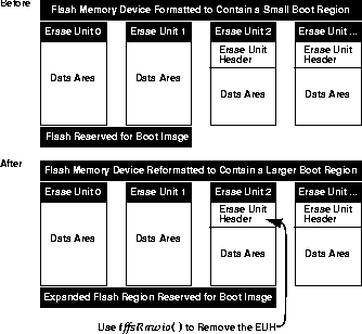
As mentioned above, when tffsDevFormat( ) formats flash above an offset, it does not touch the flash below that offset. Normally, this is a good thing. However, problems can arise if any of the erase units below the offset had previously been formatted for use by TrueFFS. These erase units would contain TrueFFS formatting headers written by an earlier call to tffsDevFormat( ).
When TrueFFS mounts a flash device, it scans the entire flash medium for TrueFFS formatting headers. It uses these headers to construct a map of the regions of flash memory that fall under its control. If the flash below the current offset happens to contain TrueFFS headers left over from a previous tffsDevFormat( ) call, the TrueFFS mount can still see these headers and will fail as a result.
To overcome this problem, you can use tffsRawio( )to do a physical erase of the problem erase units. However, this is a very powerful and dangerous utility. If misused, it can permanently damage flash memory. During the development phase of your embedded system, you can probably trust yourself to use it carefully. However, if you need to make the functionality of this utility available in the deployed version of your product, you should surround that functionality with protections appropriate to your application and its users.
Before you can create a logical TrueFFS block device, you need to have already run tffsDrv( ). If you configured VxWorks correctly, this is handled for you automatically at boot time. Running tffsDrv( )initializes TrueFFS for Tornado, which includes setting up the mutual exclusion semaphore, global variables, and data structures needed to manage TrueFFS. This initialization also includes the registration of socket component drivers for all the flash devices on the target.
Registering a socket component driver with TrueFFS starts with getting an FLSocket structure from a preallocated 5-element TrueFFS-internal array of FLSocket structures. The next step is to update that FLSocket structure to contain data and pointers to functions that handle the basic hardware interface to the flash device.
When TrueFFS needs to interact with the socket hardware for a particular flash device, it uses the drive number (0 through 4) as an index into its array of FLSocket structures. TrueFFS then uses the functions referenced in that structure to handle its hardware interface needs. Although these socket interface functions do not quite provide a block device interface, they do provide an interface that is good enough for utilities such as tffsDevFormat( ), a function you can use to format the flash medium for use with TrueFFS. This ability at this stage is important as it is not possible to create a TrueFFS block device for a flash medium that has not been previously formatted for use with TrueFFS.
After registering a socket component driver for a flash device, it is possible to create a TrueFFS block device on top of the socket component driver. To do this, call tffsDevCreate( ). As input, you must specify a number (0 through 4, inclusive) that identifies the socket component driver on top of which to construct the TrueFFS block device. The tffsDevCreate( )call uses this number as an index into the array of FLSocket structures. This number is visible later to dosFs as the driver number.
After creating the TrueFFS block device, you must mount dosFs onto the device. To do this, you must call dosFsDevInit( ). After mounting dosFs, you can read and write from flash memory just as you would from a standard disk drive. In the examples at the end of this chapter, there are no calls to tffsDevCreate( ) or dosFsDevInit( ). Instead, there is a call to usrTffsConfig( ). Internally, this function handles the call to tffsDevCreate( ), dosFsDevInit( ), and the other functions necessary to create a TrueFFS block device and mount dosFs on that device.2
1: For more information the standardized socket layer API, see 3. Writing Socket Component Drivers and MTDs.
2: To see the source code for usrTffsConfig( ), look in target/src/config/usrTffs.c.
![]()
![]()
![]()
![]()